


|
John Bubb |
|
|

|
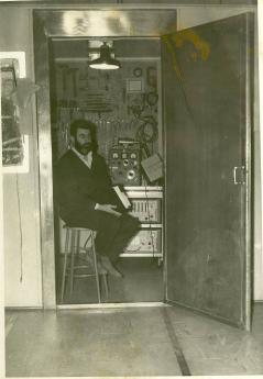
Workshop The photograph below was taken by Ivar Balsom and the following account was written by Roger Mugford. Both are used with permission. |
|
The room in the photograph is the BMEWS north screen workshop room. The entire north and south transmission rooms were each screened rooms to prevent intermodulation problems between the various assorted items of equipment. Between these two rooms were the no break room, the stores and kitchen, etc. In the north transmission room as you entered through the metal door from the rest area with the easy chairs, on the right was a small screen room which had a work bench, vice, and a very good selection of hand tools. Derek (Watkins) has his back to the work bench.
The trolley at Derek's left arm was one of two such mobile equipment set ups. The top piece of equipment, by Derek's left shoulder is a Hewlett Packard RF 900 MHz signal generator used for checking the receive sensitivity of the parametric amplifier and IF strips, thus giving the relevant fade margins at 900MHz.
This small workshop was rarely used to test equipment as it was mostly for assembly and disassembly of mechanical units, pumps, motors, etc. One small possible explanation is that once a year a Marconi calibration team arrived to check all the test equipment and would have had reason to move the trolley.
|